- Joined
- Feb 7, 2024
- Messages
- 2,822
- Reaction score
- 4,360
- Points
- 1,230
- Age
- 70
- Location (town/city + country)
- Mannum South Australia
- Driving
- MG4 (2022-2025)
First, apologies but I copied and pasted this here from the AEVA forum Converting a non working V2L to a 7kW supply from my MG4 - AEVA Forums cause I doubt I could get it right a second time, I had to redo it so many times to get that one sort of readable.
This is not intended as a guide or instructions on how to make a 7kW V2L on the cheap, this is just how I did it. If anyone chooses to follow this path, it's on you to do it safely and on your head if it doesn't work out as intended and becomes an electrical hazard ..... you have been warned
")

Ok, this is what I started out with https://www.aliexpress.com/item/1005007 ... 18026JBBa7 and looked remarkably like this one https://www.ebay.com.au/itm/37626173781 ... R_rIp5HiZQ
and naturally, it didn't work

A few hrs on Google looking at everyone's idea of what was safe, what worked and didn't work and what would happen if you didn't buy a genuine MG part, like your future birthdays would be cancelled or something ..... I lashed out and spent $4 on a mix of resistors, pulled the non working item to bits to find out why it didn't work, and discovered this
 Cheap V2L reconstruction showing original resistor and diode connected to CP pin and earth pin.jpg (129.83 KiB)
Yeah, my shaking and clear photos don't go together real well, but this I believe is the set up to make the plug into a charger ..... seems they couldn't even copy the correct thing.
So I removed the link between the earth pin (PE) and the signal pin (CP) because the common consensus was this caused false tripping sometimes, and soldered a 470ohm 1W resistor between the PE pin and the PP pin
 Cheap V2L reconstruction resistor connected to CP pin and earth pin.jpg (298.7 KiB)
and added some more heat shrink and liquid electrical tape in an attempt to avoid any shorting in the very confined enclosure
 Cheap V2L reconstruction resistor connected to CP pin and earth pin with heatshrink and liquid electrical tape.jpg (328.02 KiB)
Now comes the tricky part of getting it back together. This photo is to help verify you have the correct pins in the correct holes.
Note: I changed all the incorrectly labelled photos from CP pin to PP pin, so hopefully it comes out correct on the forum
 Cheap V2L reconstruction pins in their correct locations.jpg (217.46 KiB)
Next important step, fit the 3 screws before you try to feed the wire and pins through the body and get them located in their retainer spots and into the main body, it isn't easy once you have the wires in there
 Cheap V2L reconstruction 3 screws fitted in the body first.jpg (347.78 KiB)
It should look sort of like this when you get the pins and wires and retainer in place
 Cheap V2L reconstruction 3 screws showing with pins in place.jpg (279.96 KiB)
This is an attempt to get a photo looking down at where the screws go, just so you get an idea why I suggested to put them in first. Through the blurry photo, you can just make out the heads of the phillips screws and the now blank CP pin
 Cheap V2L reconstruction 3 screws.jpg (172.62 KiB)
This is the socket in the MG4 so you get an idea of the pin placement
 Cheap V2L reconstruction showing pin placement in vehicle socket.jpg (407.94 KiB)
You don't need photos of it screwed back together, but a note of warning, getting that multi fit socket to line up in the body without an edge catching and it buckling up, is an exercise in patience screwing each one of the 1.5 size multihex screws, one turn at a time, and tapping it every which way to get all the edges in .....
The cable to the motorhome plugged into the adaptor and into the car
 Cheap V2L reconstruction powering motorhome rooftop rattler on heat cycle drawing for MG4.jpg (401.56 KiB)
The MG4 display showing the load
 Cheap V2L reconstruction powering rooftop rattler on heat cycle draw for MG4.jpg (518.18 KiB)
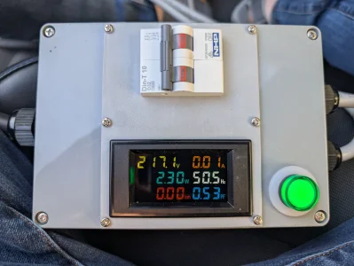
and a photo of the airconditioner in the motorhome running on heat with the outside temp at 16.5°C:
 Cheap V2L reconstruction powering rooftop rattler on heat cycle 16.5C.jpg (300.13 KiB)
This is powering the Victron inverter charger, so it is topping up the battery to power all the 12V lights and water pump, the aircon, microwave when we use it (had to try it out) the 3 way fridge on mains power, the hot water using the electric element, coffee maker, electric jug, toaster and the air fryer 9yeah tried them all, just to see if it could do it).
I'm happy with the end result, it gives us a 51kWh electrical jerry can for when we are free camping, the MG4 can be set to any 8min SOC down to 20% before it disconnects the V2L, so there will always be battery power to drive to a charger if needed, and it all works seamlessly, when the V2L drops out, the Victron inverter will draw from the 600Ah @ 12V sodium ion house battery, so the electric blanket will still be working all night and the toaster, jug and coffee machine will all work before I need to step out the door to face the day
")
Although the Victron Multiplus have an auto earth/neutral link relay connection if it doesn't sense an earth circuit on the supply side, I'll add an RVD from RVDSafe to be sure to be sure, and to protect against reverse polarity supply at a caravan park .... had that quite a few times now, so better to protect against it
T1 Terry
This is not intended as a guide or instructions on how to make a 7kW V2L on the cheap, this is just how I did it. If anyone chooses to follow this path, it's on you to do it safely and on your head if it doesn't work out as intended and becomes an electrical hazard ..... you have been warned
Ok, this is what I started out with https://www.aliexpress.com/item/1005007 ... 18026JBBa7 and looked remarkably like this one https://www.ebay.com.au/itm/37626173781 ... R_rIp5HiZQ
and naturally, it didn't work
A few hrs on Google looking at everyone's idea of what was safe, what worked and didn't work and what would happen if you didn't buy a genuine MG part, like your future birthdays would be cancelled or something ..... I lashed out and spent $4 on a mix of resistors, pulled the non working item to bits to find out why it didn't work, and discovered this
Yeah, my shaking and clear photos don't go together real well, but this I believe is the set up to make the plug into a charger ..... seems they couldn't even copy the correct thing.
So I removed the link between the earth pin (PE) and the signal pin (CP) because the common consensus was this caused false tripping sometimes, and soldered a 470ohm 1W resistor between the PE pin and the PP pin
and added some more heat shrink and liquid electrical tape in an attempt to avoid any shorting in the very confined enclosure
Now comes the tricky part of getting it back together. This photo is to help verify you have the correct pins in the correct holes.
Note: I changed all the incorrectly labelled photos from CP pin to PP pin, so hopefully it comes out correct on the forum
Next important step, fit the 3 screws before you try to feed the wire and pins through the body and get them located in their retainer spots and into the main body, it isn't easy once you have the wires in there
It should look sort of like this when you get the pins and wires and retainer in place
This is an attempt to get a photo looking down at where the screws go, just so you get an idea why I suggested to put them in first. Through the blurry photo, you can just make out the heads of the phillips screws and the now blank CP pin
This is the socket in the MG4 so you get an idea of the pin placement
You don't need photos of it screwed back together, but a note of warning, getting that multi fit socket to line up in the body without an edge catching and it buckling up, is an exercise in patience screwing each one of the 1.5 size multihex screws, one turn at a time, and tapping it every which way to get all the edges in .....
The cable to the motorhome plugged into the adaptor and into the car
The MG4 display showing the load
and a photo of the airconditioner in the motorhome running on heat with the outside temp at 16.5°C:
This is powering the Victron inverter charger, so it is topping up the battery to power all the 12V lights and water pump, the aircon, microwave when we use it (had to try it out) the 3 way fridge on mains power, the hot water using the electric element, coffee maker, electric jug, toaster and the air fryer 9yeah tried them all, just to see if it could do it).
I'm happy with the end result, it gives us a 51kWh electrical jerry can for when we are free camping, the MG4 can be set to any 8min SOC down to 20% before it disconnects the V2L, so there will always be battery power to drive to a charger if needed, and it all works seamlessly, when the V2L drops out, the Victron inverter will draw from the 600Ah @ 12V sodium ion house battery, so the electric blanket will still be working all night and the toaster, jug and coffee machine will all work before I need to step out the door to face the day
Although the Victron Multiplus have an auto earth/neutral link relay connection if it doesn't sense an earth circuit on the supply side, I'll add an RVD from RVDSafe to be sure to be sure, and to protect against reverse polarity supply at a caravan park .... had that quite a few times now, so better to protect against it
T1 Terry
Last edited by a moderator:
")