Thought I would share my spin on the 'underbed box frunk'. The issues I wanted to resolve were:
- I wan't happy cutting holes in the box for clearance
- No modifications to the car (at all)
- The boxes are pretty floppy and the plastic cracks quite easily
- It needed to be quickly dismountable if the car was going into the garage
Luckily I have a 3D printer so with a bit of design work...
The round parts fit on top of the existing posts and spread the load whilst lifting the box above that awkward clip. The other three pieces fasten together, clamping round the existing casting and give a surface at the same level as the round spacers.
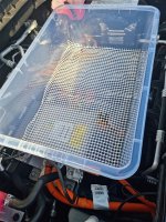
This shows the box sat on top of the mounts
The finished article. A piece of plywood sits in the bottom of the box and takes all the load, the plywood is bolted through the box into the existing threaded holes (which the spacers sit on) and the 3D printed clamp (using M3 bolts and threaded inserts in the print. Bolting like this stops the box flapping about if you accidentally hit a speed bump too fast (not that I ever have, not ever, honest)
I've had this in place since August and it is the constant home for my charging and V2L cables. It took 4m30s to dismount before the service and just 5m to refit. For any other 3D printers out there it is printed in PETG as PLA would 'creep' when used in an application like this.
I hope someone finds this useful.
") . I kept an eye on the temp over the hot weather and was surprised that the cabin was far hotter than around the inverter! Dimensional stability since the start of August has been good. It's not so much the transition temp, it's more the creep due to mechanical load that I was bothered about,
. I kept an eye on the temp over the hot weather and was surprised that the cabin was far hotter than around the inverter! Dimensional stability since the start of August has been good. It's not so much the transition temp, it's more the creep due to mechanical load that I was bothered about,
