V2L - vehicle to load adapter / cable

My SO & I were discussing V2L in the house the other day as we often have power cuts (rural village in Sussex). We agreed that a separate circuit for the car just for that purpose would be the way forward. It would have lights & a low power heater of some kind, just to keep us going. But he knows more than me about these things. 😎

Although this is a USA video, setting up VTL looks really complicated even though we have a different system here in UK! (My SO understands it.)
 
Quick question about the resistor in a V2L adapter if anyone can help?

I've just bought aV2L type 2 to 3 pin plug adapter from Aliexpress (cost me the princely sum of £15.08) and am about to change the internal resistor from the 1K that was installed, to a resistor of 470ohms, as needed for the MG.

Am I right in assuming that CP should connect directly to PE and that PP should connect to PE via the resistor?

View attachment 10473


The reason I ask is that the in the adapter as supplied, the resistor was connected directly between CP and PP (not expected) and a wire connected CP to PE (as expected).

Can I safely assume that this is basically the same configuration?
Did you get this working as I have just bought one with a 1k resistor so assume that it will not work with that value fitted

HIya
I have just purchased a similar device. Did you get yours to work after changing the resistor?
 
Hi Stefan, You've probably worked this out already but I think you have Neutral and AC phase 1 swapped on the CCS connector. See https://thedriven.io/wp-content/uploads/2019/04/CCS2-vs-type2.jpg.
Thank you Simon ! Looking your pictures, it seems so easy to make a mistake here !
Will check again my connectors, because i have earth-neutral faults on some tests. Perhaps a mistake from adapter make ?

Hi all,

Just see this on the other side of the world :

30€ all inclusive for a compact V2L adapter configured for MG EV cars.
No need to make the job ourself, now.

PS : for other EV brand's friends, they also make for KIA & co at the same price !
 
Did you get this working as I have just bought one with a 1k resistor so assume that it will not work with that value fitted
Yes, I did get it working just fine by changing the resistor to a 470 ohm one. It only needs to be a low, say 1/4w resistor as it's only a 5v signal on that line.
It's a simple mod to do.
 
Yes, I did get it working just fine by changing the resistor to a 470 ohm one. It only needs to be a low, say 1/4w resistor as it's only a 5v signal on that line.
It's a simple mod to do.
Thanks I will get mine modified

Hi all,

Just see this on the other side of the world :

30€ all inclusive for a compact V2L adapter configured for MG EV cars.
No need to make the job ourself, now.

PS : for other EV brand's friends, they also make for KIA & co at the same price !
I have bought a similar product for the MG zs. I have read on the forum that the resistance required for it to work is a 470 ohm between the pp and pe lines... ie pp to earth. The resistance measured on the one I received is 1kohm. I haven't tested it yet but suspect it will not be recognised so I intend to swap out the resistor to 470phms.
These are sold as working on the MG but I doubt it if there is a 1k ohm resistor fitted.
Has anyone bought one that works without any modification?
The company EV Cables were one of the first people to develop and bring a V2L cable to the market, after they where approached by one of the earlier owners of the ZS EV face lift models.
They both worked in conjunction with each other, to produce a cable that would work as it was originally intended by MG.
The first release / batch of these cables sold out in about 48 hours, but I was lucky to grab one of the first batch.
The second release of cables had increased in price due to the high demand for this product.
The official MG V2L adaptor was not available to order / buy in the U.K. at this point in time.
Many different types of adapters have either been made or sold by third party suppliers over time of course.
There is many companies out there right now who have quickly jumped onto the band wagon.
EV Cables where the first to produce this type of cable and are reliable.
I will try and include a link to the cable I have.

 
Last edited:
I have bought a similar product for the MG zs. I have read on the forum that the resistance required for it to work is a 470 ohm between the pp and pe lines... ie pp to earth. The resistance measured on the one I received is 1kohm. I haven't tested it yet but suspect it will not be recognised so I intend to swap out the resistor to 470phms.
These are sold as working on the MG but I doubt it if there is a 1k ohm resistor fitted.
Has anyone bought one that works without any modification?
I know: I'm one of the first to previously buy blue adapters with 1 k·ohm resistor at the wrong pins. In fact, they were not discharge adapters for MG EVs, but some other kind of adapter to have power from a stale charger. We just abused these with modifications to use on our cars :)

The ones on the link I provided at last seems to be real discharge adapters with good values for our cars. Buyers comments indicate that they work.
So it could be the great & cheap solution to have a functional adapter without making any modifications.

If this is not true, it should always be possible to correct the resistor inside.

A call for everyone : 470 ohm resistor must not be used anymore ! This a test & run value that proved to work but with no current limit (so 6KW and over !). This is not good for a normal cable.

We have to use 2 k·ohm resistor instead to limit current to something about 3 kW.
See this post : New V2L Specification MG4/MG5/ZS
(This is the EVCables guy that discovered that.)
 
Last edited by a moderator:
This week I experience a good result with my new experimental V2L -> V2H using my MG4 trophy as battery on wheels in combination with a Hongpoe 350 VDC/7A switchable power supply and a second hand Goodwe grid tie solar inverter. With two potential meter it is possible to feed the preferred power and current. Now I can compensate the needed power at the moments the sun is not shining. During the sunny days my Happy feed the MG4 with fresh "free" power.
I have one Type2 cable in the car without the resisters that are needed. I made a simple female type2 walbox and plug the preferred Type2 cable for loading (Zappi) or unloading (Hongpoe/Goodwe). It works great and is clean "Grid Tied". An ATS is added for safety if the Grid power should fail and will protect the feed back to the grid.

I also use my Omnik 2500TL inverter to do the test. It also works without any problem.
The only thing I see is that the MPPT is playing with the output in watts.
I don't know if that is a problem ?
The MG4 has no problem with this solution and works fine.
I hope that there is someone who has the same experience or have some advise to improve the stability.
 

Attachments

  • V2L-V2H.png
    V2L-V2H.png
    635 KB · Views: 131
The only thing I see is that the MPPT is playing with the output in watts.
Yeah, the MPPT want's to get the best power transfer from what it assumes is a string of solar panels. It's really not the right equipment for this job. Interesting that you got it to work at all though. It may be possible to patch the inverter's solar charge firmware to take a fixed power from the solar input.

I assume that the efficiency is fairy poor, as the car's DC gets converted to AC (in the V2L part of the EVCC), that gets converted to DC in the power supply, and that gets converted to AC in the hybrid inverter. So that's DC → AC → DC → AC. Ideally of course it all happens in one conversion stage instead of three, but then the firmware in the EVCC needs to be even smarter, and there are all sorts of regulatory hassles since the EVCC would be connected to the grid.

An ATS is added for safety if the Grid power should fail and will protect the feed back to the grid.
You should not need that if you have the right hybrid inverter. It should know to drop the relay to the AC input when the grid goes away, and that's better than relying on you to be there to switch the AT over. Meanwhile your loads on the "essential AC" port of the hybrid inverter should continue to be powered.
 
Yeah, the MPPT want's to get the best power transfer from what it assumes is a string of solar panels. It's really not the right equipment for this job. Interesting that you got it to work at all though. It may be possible to patch the inverter's solar charge firmware to take a fixed power from the solar input.

I assume that the efficiency is fairy poor, as the car's DC gets converted to AC (in the V2L part of the EVCC), that gets converted to DC in the power supply, and that gets converted to AC in the hybrid inverter. So that's DC → AC → DC → AC. Ideally of course it all happens in one conversion stage instead of three, but then the firmware in the EVCC needs to be even smarter, and there are all sorts of regulatory hassles since the EVCC would be connected to the grid.


You should not need that if you have the right hybrid inverter. It should know to drop the relay to the AC input when the grid goes away, and that's better than relying on you to be there to switch the AT over. Meanwhile your loads on the "essential AC" port of the hybrid inverter should continue to be powered.
Thank you for your reaction.
I have a little luck with the fact that I also have a old Omnik 2500 TL inverter. This inverter does the job without any software change. It is working well and gives a stability power wattage.
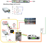
With the two potmeters (current and voltage) I can change the output I wish.

And yes...there are hybrid inverters but than you need to know whit hone works OK in this setup.
In my case I was searching for a as cheap as possible solution that works safe and do the job.
I don't want to wait any longer for a solution of the manufactures EV cars and finding and buying a new hybrid solar inverter that works.
I have to deal with the fact that I have a MG4 luxury(trophy) now with a 2.2 kW V2L inverter that gives a AC output. I also don't want to change any hardware on the car that will give any risk of warranty issues etc.
So I use existing and proven technology with a low investment and a easy way of installation.

It is not aloud but it is even possible to put a normal powerful to the output of the solar inverter that make it possible to use a normal power wall outlet at every place in your home.
20230817_232404.jpg

I took the safest way to use the proven hardware and made a Type2 wall outlet so my wife knows what she do.
A white Type2 plug of the Zappi for Loading and a green type2 for powering our home.
There is only ONE type2 plug that is plugged in the MG4 - without any resisters between the CP etc. It is straight wired to the type2 outlet.
The MG4 senses if the Zappi (loading) or V2L plug is connected.
When the Zappi is plugged in it is easy and everything works automatically. In a normal situation I use only the eco+ charging so the Zappi charge only the extra, not used, solar power into the car.

In the V2L - V2H situation You need to let the MG4 know that you want to extract power of the "power bank on wheels". So in this situation you always needs to do a extra handeling to a give manual command to the MG4. That is for me no problem.

The loss of efficiency ?? @Coulomb asked.
That is not much. When I read the input a meter it is about 600 watt. The output to the grid is about 575 watt. With that figures I can live because the sun is free and I have to pay sometimes for delivering back to the GRID.

My investment is about € 650,- I know that the TCO maybe is not right but I am happy with that.
I also have with this solution a backup power when the Grid will shutdown. A ATS will sense when this happens and switch the Solar inverter to the output of the V2L power supply.
 
Last edited by a moderator:
My SO & I were discussing V2L in the house the other day as we often have power cuts (rural village in Sussex). We agreed that a separate circuit for the car just for that purpose would be the way forward. It would have lights & a low power heater of some kind, just to keep us going. But he knows more than me about these things. 😎

Although this is a USA video, setting up VTL looks really complicated even though we have a different system here in UK! (My SO understands it.)


V2L is similar to a portable generator designed for the connection of a single appliance. As soon as two or more devices are connected there is an electrocution risk as a fault current could run from one device, through a person, to the other.

The second issue is that in the UK it is forbidden to rely on the DNO earth for 'island mode' - so a supplemental rod will be needed and connected to the main earth terminal (MET).

Thirdly the car is not phase synched with the grid so it is imperative that there is a 2-pole transfer switch between grid and the vehicle supply. The vehicle supply neutral should be bonded to the MET as part of the transfer process and this needs to be before any RCDs.

RCD protection will be needed on every circuit and type A (older AC types will not be suitable).

There are probably more considerations on top.
 
Last edited:
A picture paints a thousand words ;-)

If you can get it to work that would be great, and yet another big plus for the car.

The important thing is that when the grid is off your system must not be putting any power back into the grid. I would guess your system already takes care of this as you have batteries?

You could also use it to charge up your house batteries in the daytime using cheaper electric that you charge your car up with during the night?
Yes, any system must be able to detect when there is no power on the grid side, and any such installation must be fitted by a competent electrician for the safety of anyone working on the cables expecting them to not be live.
 
Yes it’s possible to do it. I’ve got a victron inverter and a 5kwh battery coming for peak shaving during the day. I have 1.5kw peak of solar. I intend to put the V2L adaptor onto one of the ac inputs for when our grid goes out for a while. The inverter takes care of all the switching. ATM if I lose the grid, I lose the solar since the panels have synchronous inverters, one on each. With this set up, I’ll be able to still use the solar if the grid goes down. Incidentally, it is possible to make your own lead if you are competent. The most expensive part is the Type 2 plug for the car end. The difference between a charge and discharge lead is simply an internal resistor, which tells the car which type of cable is connected.
 
This thread seems to have become a bit of a V2H thread…

I made a V2L adapter from an old AC charging lead and posted a new thread in General since it works on both our 2023 51kWh NZ market ZS EV low spec and 2024 (model year) 64kWh MG4 high spec equally well:

 
Last edited:
RCD do not work without a N to PE bound. Normally the grid system provides this N-bound. V2L can and may not have a N to PE bound. Connecting V2L via an MTS or ATS creates safety issues. V2L can be used for V2H using a transformer, in island mode. Those who have solar panels and an all in one hybrid solar inverter ( in series or parallel ) can use the GEN port of the inverter to connect V2L to the home installation. All In one inverters may have a bypass ( ATS function) and connect utility directly to the loads, bypassing the transformers. using V2l as utility this should be avoided. Grid coupled hybrid inverters have two utility ports, one for grid and one for GEN ( V2L)
 
RCD do not work without a N to PE bound. Normally the grid system provides this N-bound. V2L can and may not have a N to PE bound. Connecting V2L via an MTS or ATS creates safety issues. V2L can be used for V2H using a transformer, in island mode. Those who have solar panels and an all in one hybrid solar inverter ( in series or parallel ) can use the GEN port of the inverter to connect V2L to the home installation. All In one inverters may have a bypass ( ATS function) and connect utility directly to the loads, bypassing the transformers. using V2l as utility this should be avoided. Grid coupled hybrid inverters have two utility ports, one for grid and one for GEN ( V2L)
This is my experience.


Support us by becoming a Premium Member

Latest MG EVs video

New EVs from MG: MG S9 & MG9 plus hot topics from the forums
Subscribe to our YouTube channel
Back
Top Bottom