V2L - vehicle to load adapter / cable

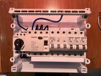
I ordered new parts to build my V2L adapter with 3-phases. Cable and schuko-socket are already there, but I am waiting for the typ2 female plug to start the build.

Oh, and our MG ZS EV too...
should be delivered in 4 weeks or so, I guess I will ask the seller again if there are some news when the car will be there
 
The UK car only has single phase.

In Europe I believe they have 3-phase supported in the car.
What I find in many of these threads , and I do it, "I believe" regarding software versions, V2L, etc etc, there must be somewhere we can find the truth...
 
What I find in many of these threads , and I do it, "I believe" regarding software versions, V2L, etc etc, there must be somewhere we can find the truth...

Okay. The European cars did have 3-phase for charging.

MG are lowering the spec for new orders of the ZS EV and the new European cars will have single phase, and the trophy version will no longer have the large sunroof.

UK cars have always had single phase for charging.

V2L is always single phase for the ZS EV.
 
Just a little quicky, can the long lead from a charging point be used as an extension for the 13amp charger, so I can reverse into, instead of driving into my drive...
Thanks anyway
 
Just the 13amp 3pin charger with the MG5, I was given a long lead to couple up to outside charging points(free ones hopefully), is it a type2?
 
No, you can't really extend a type2, you are better off getting a good quality 13A extension lead.
 
Thank you for that, I did ask the dealer the same question, but thought their answer was biased towards another sale.
 
Type two leads are designed so that they cannot be "daisy chained". The pins are arranged such that if you plug a type two lead into another type two, the pins won't reach. There are ways round it, but they would potentially leave you with live exposed pins on the lead, so not to be trifled with!
 
Quick question about the resistor in a V2L adapter if anyone can help?

I've just bought aV2L type 2 to 3 pin plug adapter from Aliexpress (cost me the princely sum of £15.08) and am about to change the internal resistor from the 1K that was installed, to a resistor of 470ohms, as needed for the MG.

Am I right in assuming that CP should connect directly to PE and that PP should connect to PE via the resistor?

1661467820579.jpeg


The reason I ask is that the in the adapter as supplied, the resistor was connected directly between CP and PP (not expected) and a wire connected CP to PE (as expected).

Can I safely assume that this is basically the same configuration?
 
Last edited:
The wires and power end up at the same point.
Why does the MG need a different resistor?
 
Why does the MG need a different resistor?
There is no standard for this (as yet), so SAIC are free to require whatever network of components there that they choose.

I suspect that they thought that by choosing their own resistor value, they'd be able to sell an MG branded cable at a nice mark-up, and drivers would have no choice other than to pay up. I guess they didn't expect the level of tinkerer that is out there.

Edit: this reminds me of the debacle some years back where laptop manufacturers would require special handshaking or whatever for their laptop chargers, hoping to carve out a captive market. But the third party manufacturers always cracked it and provided cheaper chargers that worked. Hewlett Packard, I'm looking at you.
 
Am I right in assuming that CP should connect directly to PE and that PP should connect to PE via the resistor?
The car looks at the resistance between PP and PE to determine that a discharge cable is connected. It doesn't seem to care about CP, so you can leave CP disconnected or tie it to PE, it doesn't matter.
 
It doesn't seem to care about CP, so you can leave CP disconnected or tie it to PE, it doesn't matter.
It certainly listens to CP (the Control Pilot) when charging. I think that pulling CP down to zero volts with respect to Protective Earth helps convince the charging computer that this type 2 plug insertion is not for charging.
 
Last edited:
I have tried to connect to “Central box” with RCD. Incoming Neutral and earth is connected in Ground buspar, and then Neutral goes trough RCD and then to Neutral busbar.
When I do so, the V2L stops. Like you said it automatically restarts if I pull out the plug.
A small update.
I opened the CEE conneter and terminated ground in a “isolated fix”.
Now I can connect it to my central box in my small summer cottage.
Everything is working including ground fault protection.
BUT I have no true ground. This is not good. It could not be used as everyday V2G/V2H. But maybe under emergency situations. WTSHTF
Seems interesting to have a ground fault protection.

Can u detail the entire system you have made in the end, please.
I can't schematize what you have done.

Thanks !
 
Seems interesting to have a ground fault protection.

Can u detail the entire system you have made in the end, please.
I can't schematize what you have done.

Thanks !
At the top 1-15 Neutral connections
16-30 Ground connections
Leftside L1 L2 L3 incoming

Neutral wire enters into main ground terminal 16-30, then in to ground fault switch together with the L1 L2 L3. From the ground fault switch neutral enters into neutral terminals 1-15.
All neutral lines connects 1-15
All ground lines connects 16 -30
 

Attachments

  • 639F0FA1-1DB9-441C-81E5-D77DA9095608.jpeg
    639F0FA1-1DB9-441C-81E5-D77DA9095608.jpeg
    425.3 KB · Views: 155
Thanks a lot, Adam. I understand now.
So, you create ground from neutral, but only use phase+neutral from V2L (not the ground).

Was wondering if it should work if you connect CEE neutral to your neutral busbar and CEE ground to your ground busbar, but without connecting CEE ground to CEE neutral.
In this case, V2L inverter should not auto switch off, but who know if ground fault protection is still working ?

Question : how do you test ground fault protection on your switch boxes, please ?
First. I’m not a professional. All this is what I have come to learn from researching. I’m very open to feedback.

Yes, phase+neutral without the ground.

That could be a good alternative. Connects to separate busbars. Probably the car’s protection would handle the fault protection.

I was just following how my grid is connected. Neutral and ground bonded and then separated.

I test the protection at the power socket outlet. Google: GFCI SOCKET TRSTER
 
Support us by becoming a Premium Member

Latest MG EVs video

New EVs from MG: MG S9 & MG9 plus hot topics from the forums
Subscribe to our YouTube channel
Back
Top Bottom