V2L - vehicle to load adapter / cable

This could just be a legal limitation : here, in France, for EV charging, 16A loading is not authorized on standard home socket, but limited to 10A (who said 2.2Kw at 220V ?). Why ? Because standard socket can handle 16A only for a short time ; 10A is for the long time (socket's metal oxydation).

To slow load at 16A, you must install a dedicated socket, patented by Legrand (and ultra costly).
In real world, non technical people install wallbox to load up to 11kw. Some more expert people (like me) uses 32A charger with caravan socket (can handle 32A) => this is very secure electrically but not legal because caravan socket does not have obturators in holes, but it works very well. To bypass that, you can remove sockets and direct-connect wires to switch.
But in vain : cable attached wallbox are not legal here too, because type 2 connector had no obturator holes, too ... (yes, France is a very strict normative country).

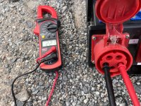
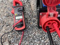
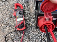
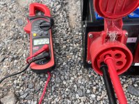
As some others here, I think than ZS inverter can handle as much as charging power : so 6kw could be possible on V2L. But that 32A so you need a good type 2 socket, with a good cable (6mm² prefered than 4mm²) to a good installation.
Nothing impossible here. You can be able to do a home backup powerbank, if you want (i want !).

But, also, as indicated on previously posted video : there's no earth.
What are dangers to people using it ?

More experimentations needed...
 
To slow load at 16A, you must install a dedicated socket, patented by Legrand (and ultra costly).
For those here who don't live in France, here's a link to the rip-off that is Legrand's socket for the granny charger.

Yes, that's 272,40€ (excluding VAT) just to plug in a granny charger - as you can see, it's no wonder people go straight for a wallbox.
 
I've just stumbled on this thread and read right through it from the beginning with big interest.
I am an electrician and am wondering firstly about the earthing situation when running an extension lead from an ev as a power supply. A power supply insulated from the ground by rubber tyres. What happens if a person using the extension lead or a device plugged into that lead the somehow comes into contact with the live conductor while standing on the ground? Is there some kind of circuit breaker in the vehicle that would trip?

I have a generator at my house that powers the whole house in event of a power cut. It's driven from my tractor and is in a shed close to the house. At the main fuse board in the house I have a 100 amp change over switch which connects either national grid to house fuse board or generator to house fuse board. Generator has enough output to run everything in my house. On the outside wall of my house I have a 63 amp plug that in use to connect to my generator with a very heavy duty extension cable when required.

This I can plug my hole house into my car with a suitable lead and switch the change over switch to the car instead of the grid and switch off all heavy load circuits at the fuse board leaving on low power essentials like lighting, boiler controls, WiFi, fridge and freezer.
 
I am an electrician and am wondering firstly about the earthing situation when running an extension lead from an ev as a power supply. A power supply insulated from the ground by rubber tyres.
In that situation, both active and neutral are insulated from earth, so touching either will not cause a lethal shock unless there is an insulation leakage to earth [ edit: from the other output ]. This could be in the appliance or at the source, in this case in the car. As you point out, it can't happen via the chassis of the car, unless the person is touching the metalwork. So it's more dangerous to use V2L power inside the car: charging a phone (but you can do that from 12V),or a laptop (harder, but can still be done from 12V), shaving (there are 12V shavers), and no doubt a few scenarios I have not thought of. But the vast majority of applications would be outside the car. You could use a residual current device for extra safety, and it will still work for those rare situations where a path via earth is possible. It won't protect against an active to neutral shock, but they don't protect against that ever.

Th[ u]s I can plug my whole house into my car with a suitable lead and switch the change over switch to the car instead of the grid and switch off all heavy load circuits...

Yes. In that situation, you should arrange for a neutral to earth link for the generator input. You of course have to be careful to only have one such connection. It may be easier to remove the generator's link, and make the link permanent at the generator input (switching neutral as well as active, so it doesn't make a second link when in grid mode). But that depends on exactly where the changeover switch is wired in. Being an electrician, you'll have no trouble sorting that out, I point this out for other readers. Neutral to earth problems can be difficult to sort out, and they can cause residual current devices to either trip all the time, intermittently, or not work when needed (the latter case is of course dangerous).

The hassle with this situation is that it's manual, you probably need to do it in the dark and/or wet, and you have to remember to turn off all the loads that would overload the V2L system. But in certain cases, perhaps rural, where power supply may be less reliable, it could be great, saving on fuel, noise, smell, maintenance etc.
 
Last edited:
I made my own from a second-hand 3phase 16A cable. I connected all cables to a 3phase CEE connector. I have 230v on all three lives, but no 400 V.
4307C2E4-FBD1-4744-AA42-DD0AE2C96FCD.jpeg
 

Attachments

  • FB9157A4-2A6B-4884-AA66-A78DBFA67707.jpeg
    FB9157A4-2A6B-4884-AA66-A78DBFA67707.jpeg
    693.5 KB · Views: 159
  • C54AD677-CDBE-4208-8263-51C4FDAA55C2.jpeg
    C54AD677-CDBE-4208-8263-51C4FDAA55C2.jpeg
    802.1 KB · Views: 160
  • 828ECDD2-787F-4E12-9A14-300E5A95982C.jpeg
    828ECDD2-787F-4E12-9A14-300E5A95982C.jpeg
    781.8 KB · Views: 893
  • EEEA1E8E-D27D-4752-933A-90E636910FD9.jpeg
    EEEA1E8E-D27D-4752-933A-90E636910FD9.jpeg
    613.9 KB · Views: 162
Last edited by a moderator:
I do find myself wondering if the car warranty will be invalidated if it comes to light that a non MG VTL adaptor has been used. You know how insurance companies like to wriggle out of paying out!
 
I do find myself wondering if the car warranty will be invalidated if it comes to light that a non MG VTL adaptor has been used. You know how insurance companies like to wriggle out of paying out!
Unless the problems is that the connector in the car is burnt to a crisp because of a bad cable, i can not see how they would know.

If i had used a good cable and the car would break i would just be adament that i only used it with an original adaptor i had borrowed. :)
 
I made my own from a second-hand 3phase 16A cable. I connected all cables to a 3phase CEE connector. I have 230v on all three lives, but no 400 V.
View attachment 8329
Did you test the voltage between any two lives? Or just lives and neutral? Just wondering if you have an effective 3 phase supply. You could run all kinds of things with a 16A 3 phase supply!!
 
Did you test the voltage between any two lives?
@adamback did say "but no 400 V". The MG EV on-board chargers are mostly single phase, so I'd expect there to be only one "front end" that can be run in reverse to become an inverting "back end".

On European models with an 11 kW (3-phase input) OBC, I'd expect a maximum of 11 kW from the V2L port. Perhaps they only make one of the "front ends" reversible, so you might get a fair bit less than that, and only single phase. [ Edit: Duh, I realise now that the three 230 V outputs have come from the V2L, not from connecting L1-L3 at the power outlet end. So that makes it more interesting. I wonder what the power limit will be? My guess is around 2.5 kW per phase. [ Edit 3: the limitation may well be the neutral conductor, since they didn't bother to space the phases 120° apart. So the neutral current, unlike true 3-phase, will be the sum of the three phase currents. ] ]

@adamback, does your model have an 11 kW on-board charger?

Edit 2: In the photo below, he's measuring phase to phase, and reading about 3 VAC. In other words, the output are all in phase, but probably not just connected together inside the car.

828ecdd2-787f-4e12-9a14-300e5a95982c-jpeg.8332
 
Last edited:
Yes, it appears to be three 240v single phase outputs and only the one neutral. This single phase but any 1 those 3 live pins could be used for the single phase circuit. It should make no difference.
Is the UK 22kw rapid charger 3 phase or single phase split across 3 conductors/pins in the lead? If it was 22kw on a single phase you'd need something like 25mm 3core lead to the car from the charger!!
 
Is the UK 22kw rapid charger 3 phase or single phase split across 3 conductors/pins in the lead?
In the UK it's 6.6 kW single phase, or about 29 A. Or it was for the Gen 1, and ev-database.org says it's the same for the standard range face-lift. But it says the long range is 7.4 kW (32 A).

For 29 A 4 mm² is adequate, but most cables are rated for 32 A, so they use slightly heavier cable.

If it was 22kw on a single phase you'd need something like 25mm² 3core lead to the car from the charger!!
Indeed. 63 A per phase (43 kW 3-phase) is considered the limit for AC charging*, and only a few cars and few "chargers" can manage it. That requires some 13 mm² cable (actives and neutral, the earth can be lighter), which is awkward and expensive. And the next highest standard metric cable size is 16 mm². But if you have one of the Zoes that has 43 kW AC charging and no DC charging, that's what you need.

* Edit: except in North America, where single phase is king. The J1772 standard goes up to 80 A, and they routinely seem to home charge at 40 A. I don't know whether there actually are 80 A vehicles or "chargers". The J1772 pins seem way too small for 80 A, or even 63 A, to my amateur eye.
 
Thus single phase but any 1 those 3 live pins could be used for the single phase circuit. It should make no difference.
You could split the load over the three outputs, thus lowering the current through the phase wires. The poor old neutral however has to take the combined current.
 
You could split the load over the three outputs, thus lowering the current through the phase wires. The poor old neutral however has to take the combined current.
But in reality it does not have to take three times the load of the phase cables, as the phases are out of sync.
 
But its not three phase its 3 x single phase so the neutral gets cooked !
Wow, so 3 single phases but not 120 degrees out of sync.

Yes, in that case, that poor neutral is getting hammered

Here, 3 phase power is 120 degrees out of sync.
 
True, but I suspect that the intention is to only use single phase loads on one of the three outputs. Though it would have made more sense to then only enable one output.
I agree, having all 3 enabled, is a potential fire hazard.
 
Have been missing the conversation here. I have the new long range with 11kw onboard charging.

Fire hazard? If I put 500w on all three “phases” , at the same time, would that give me a dangerous sync issue?

Youtuber Julian Ilett run a test with 3000w load.
 
Support us by becoming a Premium Member

Latest MG EVs video

New EVs from MG: MG S9 & MG9 plus hot topics from the forums
Subscribe to our YouTube channel
Back
Top Bottom