Mg4forluxury
Standard Member
- Joined
- May 7, 2023
- Messages
- 17
- Reaction score
- 14
- Points
- 6
- Location (town/city + country)
- Woerden the Netherlands
- Driving
- MG4 (2022-2025)
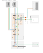
Thank you for your comment and photos. Unfortunately, it is difficult for me to form a picture of how your setup can be applied in my situation. I miss the schematic process from the V2L vcan MG to the Solar inverter.Please see attached - we've done both AC & DC coupling - currently we're in off grid mode - and awating DNO commisioning given the new rules in Sept 2022 (for the UK - for our system - ENA Type Test Register
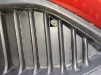
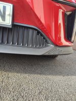
Photos attached of our decomisioned system (but the MG4 does charge the ESS battery system albeit at a selected 1KW only. )
I understand that you also use an ATS i.c.m. a capacity limiter. (set threshold value to purchase energy).
A schematic representation of your setup, showing the components used, would be of great help.
I understand that this may be asking too much, but it's nice to hear that there are other solutions for using the MG4 V2L as a "home battery on wheels"
")